District Heating Layout
Algorithm
The algorithm used to generate a possible district heating layout is Prim's algorithm.
It tries to connect every single heated building to a powerplant (located at the center of mass of the 3D model), possibly along roads.
Data from OpenStreetMap
Source
Street layouts are obtained from OpenStreetMap and used by DistrictHeatingGenerator.
OSM Data
Data is downloaded as an OSM file and saved into cache, inside repository/.cache/open_street_maps folder.
As an example, here is the header of raw_region_N48_811__E9_166__N48_814__E9_169.osm:
<?xml version="1.0" encoding="UTF-8"?>
<osm version="0.6" generator="CGImap 0.8.2 (30016 thorn-03.openstreetmap.org)" copyright="OpenStreetMap and contributors" attribution="http://www.openstreetmap.org/copyright" license="http://opendatacommons.org/licenses/odbl/1-0/">
 <bounds minlat="48.8110000" minlon="9.1660000" maxlat="48.8140000" maxlon="9.1690000"/>
 <node id="26405955" visible="true" version="8" changeset="34832583" timestamp="2015-10-24T00:26:35Z" user="Jacob's-Staff" uid="2959582" lat="48.8139649" lon="9.1672583"/>
 <node id="26422421" visible="true" version="4" changeset="81742766" timestamp="2020-03-03T19:44:00Z" user="MrKrisKrisu" uid="1214889" lat="48.8133214" lon="9.1651029">
  <tag k="railway" v="signal"/>
  <tag k="railway:signal:direction" v="forward"/>
  <tag k="railway:signal:position" v="left"/>
  <tag k="railway:signal:speed_limit_distant" v="DE-BOStrab:g1a"/>
  <tag k="railway:signal:speed_limit_distant:form" v="sign"/>
  <tag k="railway:signal:speed_limit_distant:speed" v="40"/>
 </node>
 <node id="38443922" visible="true" version="5" changeset="81742766" timestamp="2020-03-03T19:44:00Z" user="MrKrisKrisu" uid="1214889" lat="48.8138607" lon="9.1664675">
  <tag k="barrier" v="entrance"/>
...
SimStadt streets.dat
SimStadt parses the OSM street layout data and converts it to a simpler format, with one row for each road segment.
For a road segment between Node 1 and Node 2, the corresponding row will contain those values:
- Node 1 ID
- Node 1 X
- Node 1 Y
- Node 1 Z
- Node 2 ID
- Node 2 X
- Node 2 Y
- Node 2 Z
- Road type
All the coordinates are in the local coordinate reference system, as specified in the CityGML file.
As an example, for streets_N48_811__E9_166__N48_814__E9_169_EPSG_31467.dat:
# Node1 ID; Node1 x; Node1 y; Node1 z; Node2 ID; Node2 x; Node2 y; Node2 z; Way type
267345320;3512276.1068151887;5408204.575150366;1.0;2283144497;3512278.9855862185;5408198.031363033;1.0;service
2283144497;3512278.9855862185;5408198.031363033;1.0;2448503417;3512280.8895549406;5408193.909753482;1.0;service
2448503417;3512280.8895549406;5408193.909753482;1.0;2448503416;3512283.811774525;5408187.655200804;1.0;service
2448503416;3512283.811774525;5408187.655200804;1.0;318480789;3512296.27922075;5408159.302508754;1.0;service
318480789;3512296.27922075;5408159.302508754;1.0;318480912;3512302.3916302137;5408145.203752755;1.0;service
...
This file is saved in cache, inside repository/.cache/open_street_maps folder, next to the corresponding OSM file.
The filename indicates that it holds information about streets in the bounding box between (48.811°N, 9.166°E) and (48.814°N, 9.169°E), in EPSG 31467 coordinate reference system.
Modify street layouts
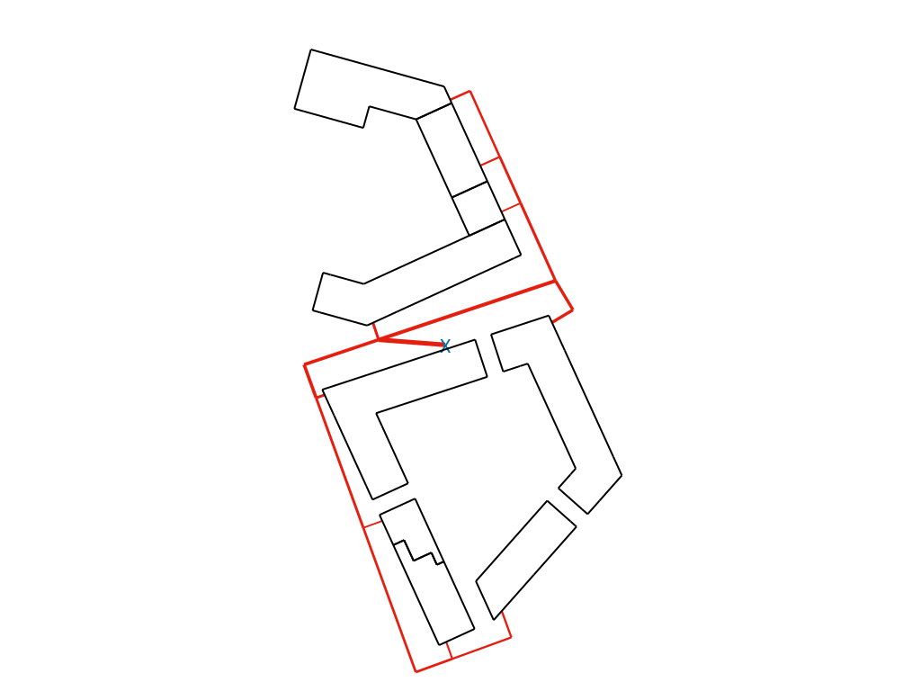
It can happen that the street layout does not fit at all with the CityGML file, for example if the 3D model describes a future project while OpenStreetMap contains information about the current street layout. The pipes (in red on the diagram) will deviate completely from the buildings (in black):
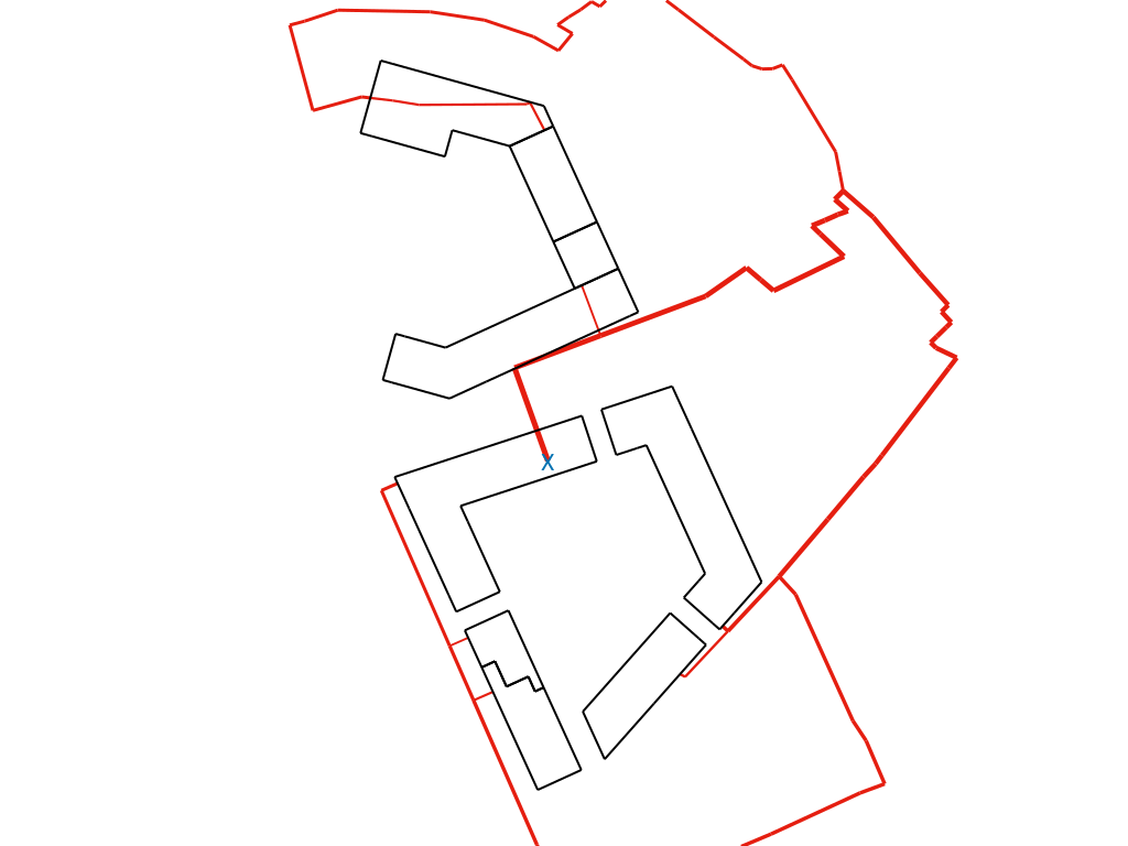
Remove roads
In that case, it might be better to delete streets from the corresponding streets____.dat file, and leave only one row in the file, preferably close to the middle of the model:
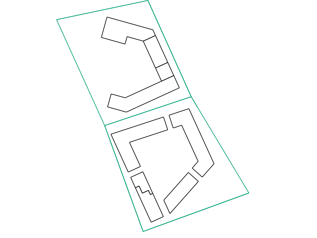
Add new roads
It is also possible to define new roads in order to better match the building footprints.
Here is the content of the corresponding streets_N48_811__E9_166__N48_814__E9_169_EPSG_31467.dat file:
1;3512280;5408490;0.0;5;3512330;5408380;0.0;fake road for future project
5;3512330;5408380;0.0;2;3512370;5408270;0.0;fake road for future project
1;3512280;5408490;0.0;4;3512375;5408510;0.0;fake road for future project
4;3512375;5408510;0.0;6;3512420;5408410;0.0;fake road for future project
5;3512330;5408380;0.0;6;3512420;5408410;0.0;fake road for future project
2;3512370;5408270;0.0;3;3512480;5408310;0.0;fake road for future project
6;3512420;5408410;0.0;3;3512480;5408310;0.0;fake road for future project
This file has been written manually, but a script could be written in order to export larger layouts from CAD or GIS programs.
Here are all the defined roads (shown in green):
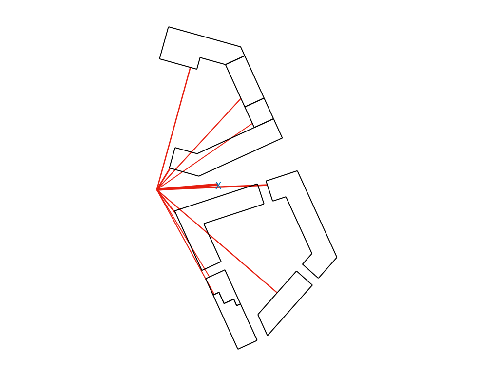
Here is the resulting district heating network, after having saved the streets file in cache and starting the simulation again:
Note that 7 new roads have been defined in the above file, but not all of them have been used for the district heating, since 4 of them were enough to connect every building.